for Brake Controller Pigtail for Winnebago Class A Motor Homes built on Ford and Workhorse Chassis (2007 and newer)
Part #EC-4129
Date: November 1, 2006 (Revised October, 2007)
Use with Unified Tow Brake Towed Vehicle Kit (TV-1000K and TVH-1000K))
2007 and newer Winnebago Class A motor homes built on Ford and Workhorse chassis are pre-wired for supplemental braking. This connector will allow the Unified Tow Brake controller to be plugged into the factory harness in the motor home so that the existing wiring can be used instead of running the Unified Tow Brake motor home harness.
Be sure the ignition is off during installation of the Brake Controller Pigtail.
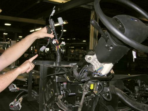
The 6-pin gray housing shown in the picture below can be accessed by removing the plastic dash pod cover located directly behind the instrument cluster.
The 6-pin Gray connector is located under the dash, forward and left of the steering column.
Plug the pigtail connector with three wires into the 6-pin Gray connector.
Find a switched 12-volt source for the remaining (red) wire that is not inserted into the pigtail connector. Splice the red wire from the pigtail into the switched 12-volt source.
Plug the other end of the pigtail into the connector from the Unified Tow Brake controller.
|
Workhorse A-Body Brake Control Connector |
||
|
Factory Harness |
UTB Wire Color |
Circuit Function |
|
LLG |
Blue |
Electric Brake Output Circuit |
|
SSK |
Black |
Ground |
|
X |
Orange |
Brake Switch Signal |
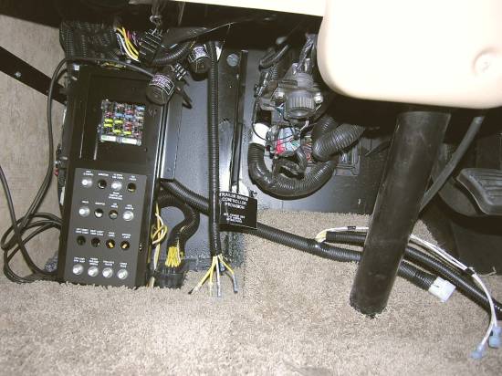
The wires listed above are located under the dash left of the steering column next to the chassis fuses & breakers.
A large black label will be attached to the end of the wire drop identifying it as the Trailer Brake Controller Provision.
Use the table above to attach the Electronic Brake Controller to this wire drop.
Cut the 6-pin connector off the EC-4129 pigtail. Connect the three wires that were attached to the connector to the factory wire drop as outlined in the table above. NOTE: Circuit identification is printed every four inches on the factory wires.
Find a switched 12-volt source for the remaining (red) wire that was not inserted into the pigtail connector. Splice the red wire from the pigtail into the switched 12-volt source.
Plug the other end of the pigtail into the connector from the Unified Tow Brake controller.
Return to Towed Vehicle Kit (TV-1000K) Operating and Installation Instructions
Return to Towed Vehicle Kit (TVH-1000K) Operating and Installation Instructions
Return to Unified Tow Brake Product Page