|
|
Unified Tow Brake (UTB-1000)
Troubleshooting Guide
How the Unified Tow Brake Works
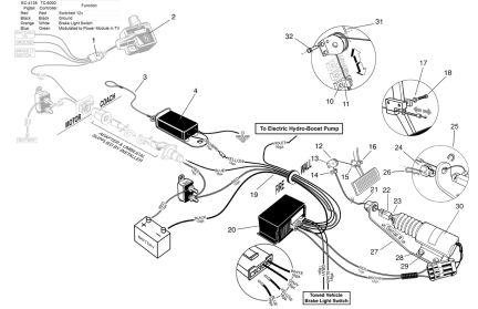
The Unified Tow Brake is comprised of several major components. The first of these is the Power Module (Part number PM-6001). The module is the control center for the brake system. Next is the Electric Solenoid (ES-6001) that is connected to the brake pedal by a Cable Assembly (CA-6001, CA-6081, or CA-6121). When electrical current passes through the coil in the solenoid, it creates a strong magnetic field and pulls the plunger down into it. The plunger is attached to the cable, which is in turn attached to the brake pedal arm (cable movement is 1-3/8").
Another component is the Vacuum Pump (VP-6000) that runs when the Power Module supplies electricity to it and the solenoid. Finally, in the towed vehicle is the Breakaway Switch (BS-6000A), which is simply a path to ground when the plunger is pulled from the switch.
In the motor home, along with the Wiring Harness, is the Brake Controller (TC-6000). The controller should be mounted to the gear shift lever (gas engine motor home), or using the dash mount provided (diesel engine motor home) on the right side of the steering wheel. There are accelerometers housed in the controller within certain angle constraints (see instructions packaged with the controller).
The function of the controller is to send braking information to the PM-6001
in the towed vehicle. The controller has two features which send the braking
signal to the towed vehicle. First is the manual control lever; it should be
used very sparingly. Using the manual control will cause the brakes in the towed
vehicle to apply at maximum. The second feature is the accelerometers which
measure the rate of deceleration electronically. In order for the accelerometers
to send the braking signal to the towed vehicle, the brake pedal in the motor
home must be depressed and a voltage signal from the stop light switch must be
present (indicated by at least one illuminated Red LED).
Lastly, there is a trickle charge wire connecting the motor home charging system to the battery in the towed vehicle to supply constant battery power for the operation of the system.
Operation and Testing
1. First, check to see that all wiring connections are consistent with the installation instructions. Then use the breakaway switch to confirm operation of system in the towed vehicle.
a. With the breakaway pin pulled, the vacuum pump runs and the solenoid pulls the brake pedal and holds until the pin is replaced. After the pin is replaced, the vacuum pump and solenoid stop working.
1. If the vacuum pump does not run and the brake pedal is not pulled:
a. Check breakaway switch for proper grounding to the circuit it is
attached to (yellow wire). Clean or replace switch.
b. Check voltage on yellow wire. It should be 9.5 to 10.5 (approximately).
If no voltage, trace wire to the PM-6001 under the dash. If no voltage
present, replace PM-6001. If there is voltage, find open in wire and
repair. Test circuit by pulling breakaway pin.
2. If the vacuum pump runs, but there is no brake pedal movement (solenoid may chatter or vibrate):
a. Re-insert pin into breakaway switch. Attach volt meter to brown wire between the solenoid and the PM-6001. Pull pin and watch voltage at brown wire. In the first stage, there should be about 1v for about two seconds. In stage 2, there should be between 2.5v and 3.5v for about two seconds. In the third stage, voltage should level off between 4 and 5 till the pin in the breakaway switch is re-inserted. If PM-6001 does not respond as outlined, replace and re-test.
3. Breakaway switch works as designed, but no braking signal from motor home, either using the manual lever, or automatically by depressing the motor home brake pedal when the coach is in motion.
a. Verify that the Green LED on the TC-6000 is illuminated when the towed vehicle is electrically connected to the coach.
1. If no LED illuminated, turn key off in coach and back on again. Green LED should flash on and off, the four Red LEDs should illuminate one at a time right to left, and then go out. Then the Green LED should remain illuminated. If none of this has happened, check for power (voltage) wire, and check for good ground (green wire). Repair and re-test.
2. If the TC-6000 responds to key power up from the motor home, but the Green LED is not illuminated indicating connection:
a. Unplug controller; check voltage on blue wire at harness ? should be 9.5 to 10.5 volts. If no voltage, backtrack to PM-6001 until a break in the wire is found. Repair and re-test.
b. If voltage is present, plug in the TC-6000 to harness. Check voltage on both sides of plug. Repair as necessary. If voltage reduces to lower than 9.5 to 10.5, replace the TC-6000 and re-test.
b. If Green LED on the TC-6000 is illuminated, and Red LEDs respond to manual lever movement (or braking of moving coach):
1. Check voltage on the blue wire again. Move manual lever to maximum, and with motor home key on, voltage should reduce to about 1v. If there is no reduction, replace the controller and re-test.
Testing Automatic operation with Green LED illuminated and towed vehicle connected.
Use volt meter on blue wire again. Remove controller from mount. Depress motor home brake pedal and move the controller back and forth quickly in your hand. LEDs should increase and decrease with movement, and voltage should change on blue wire. This is a less reliable testing method. It is better to drive the motor home with the controller in place and do a series of braking attempts, and watch the voltage change.
Voltage Values at Various Components
1) Power Module (PM-6001)
1. Large red wire from battery through 40 amp circuit breaker - should be battery voltage (at least 12.6 volts)
2. Large black wire - good ground, either to engine block or battery negative terminal
3. Large brown wire is ground side of electric solenoid - voltage should vary from less than 1 to 10 or 11, depending on ground provided by PM-6001. Lower voltage strengthens solenoid pull.
4. Violet/Red wire - same voltage as red wire when breakaway pin pulled or manual control lever used from motor home
5. 4-Wire connector to PM-6001
a) left wire (blue) - 9.5 volts to 10.5 volts to TC-6000
b) next wire (yellow) - 9.5 volts to 10.5 volts to breakaway switch
c) next wire (gray) - may or may not be used. No testing required.
d) right wire (white) - may or may not be used. No testing required.
2) Controller in motor home (TC-6000)
1. Red wire - both sides of plug should have 12 volts with keyed power
2. Black wire - both sides of plug, good ground
3. Orange to white wire - 12 volts when motor home brakes applied
4. Blue to green wire - 9.5 to 10.5 volts, and will vary with operation. Voltage originated in PM-6001 through blue wire
3) Vacuum pump (VP-6000)
1. Violet wire to pump connector - 12 volts when brake working, power to solenoid also from PM-6001
2. Black wire - good chassis ground
4) Breakaway switch (BS-6000A)
1. Orange/brown wire to yellow wire at switch connector - 9.5 to 10.5 volts all the time from PM-6001
2. Black wire - good chassis ground
Mechanical Operation
1. Solenoid operation - Plunger must be free to move in and out of the solenoid. Cable must enter the solenoid stop (#24 on component rendering) straight through the groove and slot
2. Cable should not bind due to sharp bends or kinks in the cable. If it is necessary to put loops or turns in the cable to use up excess cable length, tape cable to bare floor with duct tape.
3. Inner cable must exit the cable end bracket (#14 on component rendering) without dragging the side of the outer cable or bracket. The bracket (#14) must aim or direct the inner cable straight to the groove at the bottom of the pulley (#12). Align the pulley so it clears the brake pedal arm and/or bracket attached to the brake pedal arm (#15 and #16).
|
|