D-Celerator Diesel Exhaust Brake Operating and Installation Instructions
READ THIS MANUAL BEFORE ATTEMPTING
TO INSTALL D-CELERATOR.
PLEASE REGISTER SERIAL NUMBER OF UNIT
BY SENDING WARRANTY CARD TOModel #_______________
Serial #_______________Form USG-EXB (06/08)
D-CELERATOR? Diesel
Exhaust Brake
"SUPER-DUTY MODEL" OPERATING
INSTRUCTIONS
| NOTICE: This device is not designed for use while the cruise control system of your vehicle is turned on. |
The controls that operate your new D-Celerator? consist of two driver-interactive components. First is the pushbutton "on/off" switch. Second is the D-Feat device. The D-Feat device is connected to the use of your throttle so that when you depress the accelerator, your D-Celerator? is automatically disengaged. When you release the accelerator, the D-Celerator? begins to function again. The D-Feat device consists of a D-Feat wire or a Microswitch.
To engage the D-Celerator? just press the pushbutton on/off switch. With your foot off the throttle, the red light located behind the U.S. Gear logo will illuminate solid. This means that the D-Celerator? is braking. To turn off the D-Celerator? , press the on/off switch again and the red light will go out.
Once the D-Celerator? is on, you will also be able to control the operation of the exhaust brake by using your D-Feat device. To temporarily disengage the D-Celerator? , apply pressure to the accelerator. While the D-Feat device is operational, the red light on the pushbutton on/off switch will flash continuously. To reactivate the D-Celerator? , release the accelerator.
To achieve maximum braking horsepower once the D-Celerator? is engaged, shift to a lower gear and keep your RPMs up. If you need less braking assistance, shift to a higher gear or turn the unit off. Use the pushbutton switch to turn the D-Celerator? off if you are not accelerating your vehicle.
| WARNING: The D-Celerator? is designed only to assist your vehicle brakes. At no time is the D-Celerator to be used instead of, or to replace, your factory equipped vehicle wheel brakes. |
The Cycle Feature is an exclusive self-maintenance characteristic of the D-Celerator? which you will notice when you turn your ignition to the on position. The red light on the pushbutton will flash for fifteen seconds after you turn the ignition on. Then the D-Celerator? will cycle on and off twice. You may bypass the Cycle Feature by pressing the accelerator during the fifteen seconds that the light on the pushbutton is flashing. CAUTION: Do not use the bypass feature on a consistent basis. Regularly canceling the cycle feature combined with a lack of use of the exhaust brake could cause damage to your D-Celerator? .
NOTE: Due to soot build-up, it may become necessary to re-lubricate the large butterfly pivot shaft bushings in the D-Celerator Diesel Exhaust Brake. We recommend that this service be performed on a regular basis according to use (normally every couple of years).
|
If you have any questions concerning the operation or use of the D-Celerator?, please call your U.S. Gear Customer Service representative at1-800-USGEAR-1 (1-800-874-3271) |
D-Celerator?
Installation Manual
For Diesel Powered Pick-ups, Vans &
Motorhomes
Before installing the D-Celerator? Main Housing in the exhaust system, first you should run the Main Wiring Harness down through the driver side engine compartment. Starting on top of the engine compartment and feeding the Wiring Harness down along the fire wall.
NOTE: BE SURE NO PART OF THE WIRING HARNESS IS TOUCHING ANY COMPONENTS THAT PRODUCE HEAT (ENGINE, EXHAUST, ETC.) OR ANY MOVING COMPONENTS IN WHICH THE HARNESS MAY GET CAUGHT OR TANGLED (STEERING SHAFT, ETC.).
UNDER THE VEHICLE
Raise the vehicle to a working height and secure with jack stands. Somewhere
ahead of the muffler, locate a straight section of tubing approximately
11-13" long. Verify that the wiring harness will reach the desired location
before cutting the exhaust pipe. Using a hacksaw or Sawsall works best for
cutting the pipe.
|
2?", 3", and 3?" Applications Cut an 8" straight section out of the exhaust pipe leaving 1?" of straight pipe on each end of the remaining tubing. Clean burrs and dirt from both the front and rear exhaust pipes left hanging in preparation for installing the D-Celerator ? Main Housing.NOTE: BE SURE THAT THE STOCK EXHAUST IS NOT DEFORMED ON THE ENDS BEING USED FOR INSERTION INTO THE D-CELERATOR? MAIN HOUSING.Using a tape measure and marker, draw a line 1?" back from the end of the front pipe and the back pipe. These lines will help you center the D-Celerator? Main Housing in the proper fore and aft position. |
4.0" Applications On 4.0" applications be sure to observe the following changes in the measurements when cutting the exhaust pipe. Also, leave 1?" of straight pipe on each end and cut a 9?" section of pipe from the middle of the 13" section. NOTE: ON 4.0" REAR-ENGINE APPLICATIONS YOU WILL USUALLY FIND A PIECE OF FLEX TUBE BETWEEN THE ENGINE AND THE MUFFLER FRAME HANGER. BE SURE TO INSTALL THE D-CELERATOR ? IN FRONT OF THE FLEX TUBE. |
Locate the INLET end of the D-Celerator? Main Housing ("Inlet" or "Flow" arrow is cast in the Nodular Iron Main Housing.) This end will be installed closest to the vehicle engine.
NOTE: LEAVE FRONT ADAPTER AND CLAMP ATTACHED TO MAIN HOUSING.
| NOTE: BE SURE THAT NO PART OF THE D-CELERATOR? IS TOUCHING THE FRAME, CROSSMEMBERS, OR TRANSMISSION. THE D-CELERATOR MAIN HOUSING WAS DESIGNED TO BE ROTATED AROUND ITS AXIS TO ALLOW PROPER CLEARANCE. |
Slip the wide band clamp and the outlet pipe adapter on the rear portion of the factory outlet pipe. Slip the second wide band clamp onto the front pipe; then insert exhaust brake inlet into front pipe.
Line up the front adapter with your centering mark. Using the V-Clamp, re-attach the rear pipe adapter to the casting. Be sure the V-clamp is securely tightened.
Once you have the D-Celerator? Main Housing connected to the front and back stock exhaust pipes, move Main Housing forward or backward to locate lines that were drawn earlier. This centers the coupling of the Main Housing to the stock exhaust pipes.
| ATTENTION: Rubber nipple on waste gate actuator canister is simply a plug; do not remove. |
Now, rotate the assembly to a position where you can easily connect the MAIN WIRING HARNESS to the actuator assembly and tighten the band clamp bolts to approx. 60 ft. lbs of torque. Refer to the Clamp Installation Procedure. Plug in the wiring harness into the actuator assembly. On electric activated models you will need to attach the "Green" ground wire to the frame. NOTE: FOR PROPER GROUND, YOU WILL NEED TO SCRAPE THE PAINT ON THE FRAME AROUND THE MOUNTING HOLE. BARE METAL IS REQUIRED!
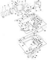
Click on the picture or here to
go to the mechanical components page.
|
D-CELERATOR? CLAMP INSTALLATION PROCEDURE
2. Position D-Celerator? main housing in proper fore and aft position. 3. Position top edge of clamp flush with
top edge of end cap. 4. Tighten nut until clamp is snug on end caps. 5. Check to be sure top edge of the clamp
is flush with the top of the end caps. 6. FINISH TIGHTENING NUT TO APPROX. 60 FT. LBS.
|
ELECTRICAL INSTALLATION
NOTE: Care should be taken to insure
the protection of the loom when going through the fire wall.
Install the D-Feat mechanism (Wire or Microswitch) according to its instructions.
|
|
The Electronic Control Module (ECM) must be installed in a dry location since it is not weatherproof. On front-engine applications, secure the ECM in a concealed location under the dash. On rear-engine applications, install the ECM in a location which is protected from the elements (rain, road spray, etc).
After making sure the wire from the pushbutton on/off switch will reach the ECM, mount the pushbutton in a convenient location and plug the small 3-prong connector into the mating connector on the ECM. Allow the customer to decide on the location of the pushbutton, if possible. Position the hole in the center of the U.S. Gear decal over the LED light on the pushbutton and affix the decal to the pushbutton.
Install the wiring according to the schematic on the electronic components page.
NOTE: BE SURE THAT THE FUSE POSITION IS "HOT" ONLY WHEN THE IGNITION IS "ON".
This completes the installation of the U.S. Gear "Super-Duty Model" D-Celerator? Diesel Exhaust Brake.
 1.
Place clamps over D-Celerator? end caps.
1.
Place clamps over D-Celerator? end caps.